Understanding DPF Differential Pressure
Differential pressure is one of the most useful pieces of DPF diagnostic information available on a modern diesel. It is also one of the easiest readings to misread, because a single figure on its own says very little - exhaust flow, sensor integrity and test conditions all have to be accounted for before the number means anything.
The sensor itself only measures a pressure difference. What that figure means is decided by the ECU, which weighs it against operating conditions and its own DPF control strategy, not read in isolation.
A pressure reading is only as good as the flow, sensor and conditions it was recorded under.
What is being measured
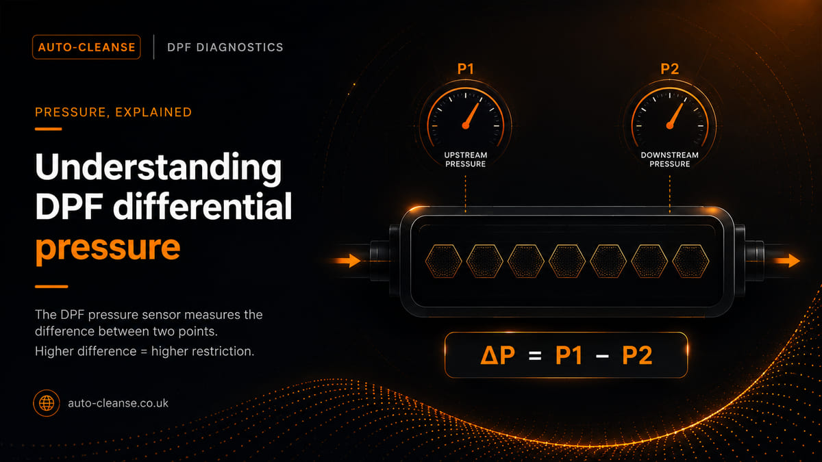
A differential pressure sensor compares pressure at two points in the exhaust system, commonly upstream and downstream of the DPF. Depending on the application, this may be achieved through two separate pressure connections or through a different sensor arrangement defined by the manufacturer.
- Upstream - exhaust pressure before the monitored restriction.
- Downstream - exhaust pressure after the monitored restriction.
- Difference - the pressure drop reported to the ECU.
Why exhaust flow changes the picture
As engine speed and load change, exhaust mass flow changes, and the pressure drop through the filter changes with it. A reading taken at idle cannot be fairly compared with one taken at raised engine speed, during a road test, or on another engine, without accounting for the conditions each was recorded under.
Lower flow: less diagnostic separation
At low exhaust flow the pressure difference may be small, giving limited separation between filter conditions. Sensor resolution and offset become especially important at this end of the range.
Higher flow: restriction becomes more apparent
Under a controlled higher-flow test, restriction may become easier to identify. The correct test speed, load and limits remain application-specific, so the manufacturer procedure should set the terms of the test.
Common misdiagnosis: treating one pressure figure as proof that the DPF is blocked. A value without engine speed, load, temperature, measurement units and vehicle-specific limits has very little diagnostic context on its own.
Verify the complete sensing system before trusting the number
A pressure figure is only as reliable as the system that produced it. Before accepting it as evidence for or against a blocked filter, each part of the sensing system needs to be checked as part of a proper DPF diagnostic check:
- Sensor plausibility. Use the manufacturer's procedure to check the sensor at rest and while pressure changes, confirming the displayed value responds smoothly and plausibly rather than assuming a stored code proves the sensor itself has failed.
- Pressure pipes and hoses. Check the path to the sensor for blockage, soot contamination, condensation, heat damage, splits, kinks, incorrect routing and loose connections - a sound sensor cannot report the correct pressure if the pressure path is compromised.
- Electrical integrity. Inspect wiring and connectors, then carry out the circuit tests specified for the vehicle; corrosion, poor terminal tension, damaged wiring or an incorrect reference supply can all create implausible pressure information.
- Exhaust integrity. Look for leaks, damaged pressure take-off points, a cracked filter or an incorrectly assembled exhaust, any of which can alter the pressure relationship. A low reading does not automatically prove the DPF is healthy.
Reading the figure in context
Pressure is supporting evidence, not the whole diagnosis. Before drawing a conclusion from it:
- Confirm the units. Scan tools may display pressure using different units and scaling.
- Record the conditions. Engine speed, load and temperature all matter when comparing results.
- Review supporting data. Soot estimates, regeneration history, temperatures, air-path faults and relevant DTCs.
- Consider filter history. Soot, non-combustible ash and physical damage can affect restriction differently.
- Use the correct specification. Manufacturer procedures take precedence over generic figures.
If the full picture points to a genuinely blocked DPF rather than a sensor or plausibility issue, that is the point at which removal for off-vehicle cleaning becomes the appropriate next step, rather than the pressure figure alone.
The takeaway
A differential pressure reading only becomes meaningful when the measurement system and test conditions behind it are credible. Use it as part of a complete DPF assessment, not as a stand-alone blockage number.
Sources
- Bosch Mobility - Differential pressure sensor operating principle and DPF charge monitoring
- HELLA TechWorld - DPF differential pressure monitoring and exhaust aftertreatment diagnostics
- NTK Vehicle Electronics - Exhaust and differential pressure sensor function
- SAE technical research - Pressure drop varies with soot, ash, exhaust flow and filter conditions
- EPA HERO research index - Conventional DPF control uses pressure-drop measurements and predictive models to estimate loading
General technical guidance only. Sensor layout, test conditions, diagnostic limits, displayed units and DPF control strategies vary by manufacturer, engine and ECU software. Manufacturer workshop information always takes precedence.
Need help with this on your vehicle?
Auto-Cleanse can sort it. See our DPF Diagnostics service, or get in touch.
Related: Blocked DPF Cleaning · DPF Cleaning in Devon